Injection of CO2 into a reservoir may cause an increase in the reservoir pressure or stress alterations in the subsurface. These changes may result in small displacements of the ground surface above the reservoir. Highly precise surface displacement measurements can be used to monitor this deformation.1National Energy Technology Laboratory. (2017). Best practices: Monitoring, verification, and accounting (MVA) for geologic storage projects. National Energy Technology Laboratory, U.S. Department of Energy. https://netl.doe.gov/sites/default/files/2018-10/BPM-MVA-2012.pdf
InSAR (Interferometric Synthetic Aperture Radar) is a satellite-based technique that measures millimeter-scale displacements of the Earth’s surface by recording microwaves as they are reflected off permanent, solid features on the ground. The amount of surface displacement due to increase in pressure or changes in stress resulting from CO2 injection is typically small, for example surface uplift less than 1 mm is not measurable by InSAR. But greater uplift may be indicative of surface movement related to injection of CO2, and InSAR can detect these changes.2National Energy Technology Laboratory. (2017). Best practices: Monitoring, verification, and accounting (MVA) for geologic storage projects. National Energy Technology Laboratory, U.S. Department of Energy. https://netl.doe.gov/sites/default/files/2018-10/BPM-MVA-2012.pdf
InSAR methods work well in locations with level terrain, minimal vegetation, and minimal land use. Large areas, up to 10,000 km2, can be imaged in a time-lapse manner to evaluate surface displacement occurring over a given time period. The frequency of the time-lapse monitoring depends on how often the satellite passes over the area of interest.3National Energy Technology Laboratory. (2017). Best practices: Monitoring, verification, and accounting (MVA) for geologic storage projects. National Energy Technology Laboratory, U.S. Department of Energy. https://netl.doe.gov/sites/default/files/2018-10/BPM-MVA-2012.pdf
Surface Deformation Monitoring Summary
- Description: Monitor surface deformation caused by reservoir pressure changes or geomechanical impacts associated with CO2 injection. Measurements made with satellite-based radar (SAR/InSAR) and surface- and subsurface-based tiltmeters and GPS instruments. Data allow modeling of injection-induced fracturing and volumetric change in the reservoir.
- Benefits: Highly precise measurements over a large area (100 km x 100 km) can be used to track pressure changes or geomechanical impacts in the subsurface associated with plume migration. Tiltmeter technology is mature, and has been used successfully for monitoring steam/water injection and hydraulic fracturing in oil and gas fields. GPS measurements complement InSAR and tiltmeter data.
- Challenges: Tiltmeters and GPS measurements require surface/subsurface access and remote data collection. InSAR methods work well in locations with level terrain, minimal vegetation, and minimal land use, but must be modified for complex terrain/ varied conditions. Surface displacement responds also to groundwater withdrawal and recharge and to non-injection related process such as local to regional subsidence and uplift. Movement may not indicate risk, must be coupled with complex 3-D geomechanical models to make results actionable. 4National Energy Technology Laboratory. (2017). Best practices: Monitoring, verification, and accounting (MVA) for geologic storage projects. National Energy Technology Laboratory, U.S. Department of Energy. https://netl.doe.gov/sites/default/files/2018-10/BPM-MVA-2012.pdf
Application
A very significant application of InSAR is at the In Salah Project in Algeria. The CO2 injected is a result of gas processing from In Salah Field. The dry gas produced contains 5.5% of CO2. The produced gas is sent to a facility for reducing the CO2 content before the gas is sent via pipeline for local and international export.5MIT. (n.d.). In Salah fact sheet: Carbon dioxide capture and storage project. Retrieved July 1, 2021, from https://sequestration.mit.edu/tools/projects/in_salah.html The ground surface at In Salah is rocky desert, which is suitable for InSAR. The satellite used at In Salah provided a revisiting time of 12 days.6National Energy Technology Laboratory. (2017). Best practices: Monitoring, verification, and accounting (MVA) for geologic storage projects. National Energy Technology Laboratory, U.S. Department of Energy. https://netl.doe.gov/sites/default/files/2018-10/BPM-MVA-2012.pdf


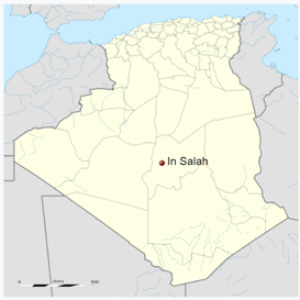
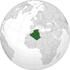
The In Salah Field is located in the Saharan desert in central Algeria, northwest Africa. Algeria exports gas on the international market to countries such as Italy and Spain.7In Salah. (2021, May 5). In Wikipedia. https://en.wikipedia.org/wiki/In_Salah8Algeria. (2021, July 1). In Wikipedia. https://en.wikipedia.org/wiki/Algeria
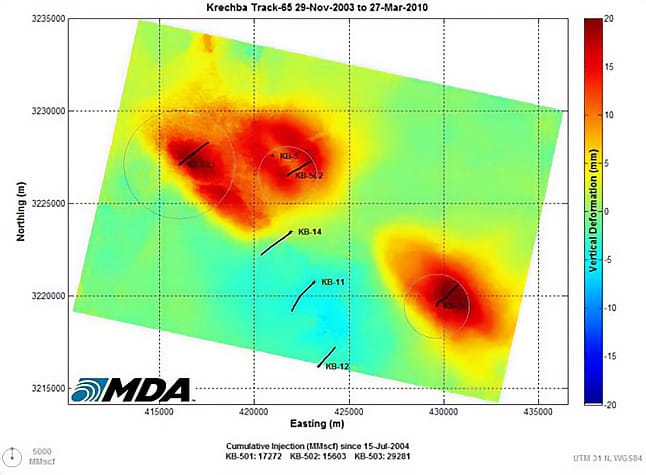
Analysis of data through time shows growth of spatially delineated uplifts overlying the injection wells at rates of up to 5 mm/year, with cumulative uplifts in excess of 20 mm.9National Energy Technology Laboratory. (2017). Best practices: Monitoring, verification, and accounting (MVA) for geologic storage projects. National Energy Technology Laboratory, U.S. Department of Energy. https://netl.doe.gov/sites/default/files/2018-10/BPM-MVA-2012.pdf Surface uplift has been detected over all three of the In Salah CO2 injection wells with corresponding subsidence also observed over the gas production area.10Sevket D., Ji-Quan S., Caglar S., & Korre, A. (2011). In Salah CO2 storage JIP: Carbon dioxide plume extension around KB-502 well–New insights into reservoir behaviour at the In Salah storage site. Energy Procedia, 4, 3379-3385. Deformation may have involved widening of a conductive fault. Analysis of the reservoir, seismic and geomechanical data from 2010 led to the decision to suspend CO2 injection in June 2011.11MIT. (n.d.). In Salah fact sheet: Carbon dioxide capture and storage project. Retrieved July 1, 2021, from https://sequestration.mit.edu/tools/projects/in_salah.html

Satellite image of cumulative surface deformation at In Salah Project due to CO2 injection. Surface displacement measurements are designed to detect uplift of the land surface that may have been caused by CO2 injection within the storage formation. Vertical deformation is mapped in mm, with hot colors indicating higher levels of vertical displacement. Three CO2 injection wells are shown: KB501, KB502 and KB503 (located within the core of the greater deformation zones). Other wells in the diagram are production wells.12National Energy Technology Laboratory. (2017). Best practices: Monitoring, verification, and accounting (MVA) for geologic storage projects. National Energy Technology Laboratory, U.S. Department of Energy. https://netl.doe.gov/sites/default/files/2018-10/BPM-MVA-2012.pdf