Core samples used as part of a monitoring program represent a cylindrical section of rock (deep subsurface) or soil (near surface). Scientists and engineers obtain cores by various techniques: drilling with special drills and hollow steel tubing into rock, or in the cases of soft material on land (e.g., soil), by driving a hollow pipe for sampling. As part of the coring process, the sample is pushed more or less intact into the tube, removed from the tube in the laboratory, and then inspected and analyzed by different techniques and equipment depending on the type of data desired. 1Core sample. (2021, February 24). In Wikipedia. https://en.wikipedia.org/wiki/Core_sample
Core Analysis Summary
- Description: A cylindrical section of rock (deep subsurface) or soil (near surface).
- Benefits: Highly precise measurements can be obtained on rocks and soils to assist in the monitoring process, such as porosity, permeability, fluid content, soil-gas components. Data can be used to calibrate remotely derived data, such as logs and seismic.
- Challenges: Collection of cores, especially those from deep in the subsurface, can be extremely expensive. Depending on the geology of the region, some cores may be technically difficult to collect or retrieve. Cores must be properly marked and archived to ensure that measurements are properly calibrated.
Application
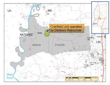
In July 2008, Denbury, an oil and gas operator, began CO2-EOR operation at the Cranfield Oil Field located 20 km east of Natchez, Mississippi. Through funding from the U.S. Department of Energy, a number of research partners were able to deploy a variety of monitoring technologies focused on a commercial CO2 injection environment at the site. The Cranfield Project safely demonstrated large-scale, long-term CO2 injection and storage in a CO2-enhanced oil recovery and associated saline reservoir between 2009 and 2015, during which time 5,371,643 t of CO2 were successfully stored.2National Energy Technology Laboratory. (n.d.). Cranfield Project: Lower Tuscaloosa Formation, Natchez, Missippipi Southeast Regional Carbon Sequestration Partnership. Retrieved July 1, 2021, from https://www.netl.doe.gov/sites/default/files/2018-11/Cranfield-Project.PDF 3Lu, J., Kordi, M., Hovorka, S. D., Meckel, T. A., & Christopher, C. A. (2013). Reservoir characterization and complications for trapping mechanisms at Cranfield CO2 injection site. International Journal of Greenhouse Gas Control, 18, 361-374.

Location of the Cranfield Project east of Natchez, Mississippi. The yellow highlighted area in the inset map of Mississippi is the location of Jackson Dome, the source of the CO2 injected at Cranfield.4National Energy Technology Laboratory. (n.d.). Cranfield Project: Lower Tuscaloosa Formation, Natchez, Missippipi Southeast Regional Carbon Sequestration Partnership. Retrieved July 1, 2021, from https://www.netl.doe.gov/sites/default/files/2018-11/Cranfield-Project.PDF
Carbon dioxide was injected into the Tuscaloosa Formation, a 15-m thick sandstone. Multiple laboratory studies on cores taken from wells at the site allowed scientists to test the capacity of the Tuscaloosa Formation to hold large volumes of CO2. As part of the study, drill cores were described and logged.5Lu, J., Kordi, M., Hovorka, S. D., Meckel, T. A., & Christopher, C. A. (2013). Reservoir characterization and complications for trapping mechanisms at Cranfield CO2 injection site. International Journal of Greenhouse Gas Control, 18, 361-374.

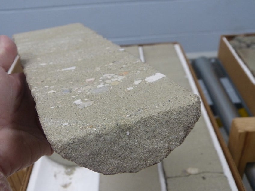
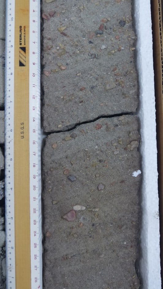
Two different core intervals from a Cranfield Project well set up for viewing at the Bureau of Economic Geology at The University of Texas at Austin. Core samples are usually cut in half vertically, as shown here, to facilitate viewing of different features of the rock (e.g., grain sizes, grain types).

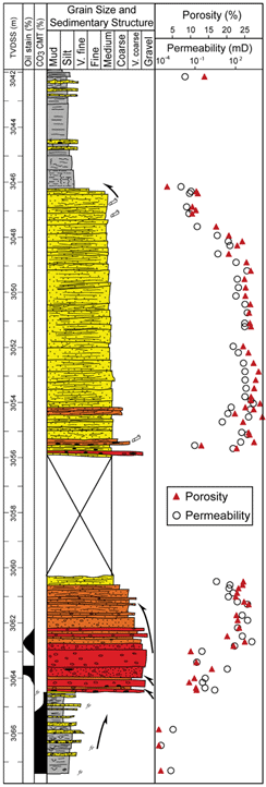
Samples were taken from the cores for a number of measurements, including porosity and permeability. These data enabled a better understanding of the injection zone, and allowed for better prediction and monitoring of reservoir and CO2 interactions.6Lu, J., Kordi, M., Hovorka, S. D., Meckel, T. A., & Christopher, C. A. (2013). Reservoir characterization and complications for trapping mechanisms at Cranfield CO2 injection site. International Journal of Greenhouse Gas Control, 18, 361-374.

A geologist’s visual description (left side) of core from well #29-12 at the Cranfield Project. Samples from this core were measured for porosity and permeability (right side). Intervals of core with higher porosity tend to allow greater volume of CO2 storage, and intervals with higher permeability tend to allow greater rate of CO2 injection. Porosity values of ~25% and permeabilities of 102 mD (e.g., at 3051 m) are considered excellent targets for injection. Large X indicates no core recovered at these depths in the well. TVDSS = true vertical depth subsea. Permeability measured in millidarcies (mD).7Lu, J., Kordi, M., Hovorka, S. D., Meckel, T. A., & Christopher, C. A. (2013). Reservoir characterization and complications for trapping mechanisms at Cranfield CO2 injection site. International Journal of Greenhouse Gas Control, 18, 361-374.
Image Credits
- core part 1: Hilary Olson
- core part 2: Hilary Olson