As part of the design challenge you will take the place of a drilling engineer. You will be responsible for estimating the pore pressure and fracturing pressure gradients for your well, which define the mud weight window. Knowing that information, you will determine what mud weight will be needed to safely and economically drill the well. Finally, you will determine the appropriate casing set point depth for your well, which will determine how many casing strings you need to complete your well, and how many feet of different diameter pipe you need to purchase for well construction.
Pore Pressure and Fracture Pressure
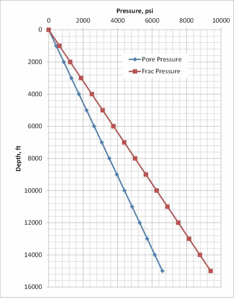
The two pressures we must determine for the mud weight window are the formation pore pressure and the formation fracture pressure. Figure 1 is a simple example of how these pressures can vary with depth. Actual pressures for a given region may be determined by referring to pressure data from existing wells already drilled, or by doing modeling based on the geology of the basin. A normally pressurized sequence of geology will have a pressure gradient close to 0.433 psi/ft, which we have already learned is the expected hydrostatic pressure gradient for a column of freshwater. Hydrostatic pressure calculation principles work similarly in the fluid filled pore space in rocks as they do in the column of fluid that fills the wellbore.

Figure 1. This chart shows pore pressure (psi) and fracture pressure (psi) increasing as a function of depth (ft).
Looking at the chart in Figure 1, determine first whether the slope of the pore pressure curve is constant with depth, and then determine the magnitude of that slope, which we would call the pore pressure gradient.
Is the slope constant?
Yes
Correct.
No
Incorrect.
Estimate the slope magnitude for the pore pressure curve.
0.44 psi/ft
Correct.
.44 ft/psi
Incorrect.
4,400 psi
Incorrect.
None of the above
Incorrect.
Notice that the fracturing pressure curve in Figure 1 is also a straight line, indicating a constant slope for the line which means a constant fracturing pressure gradient. Looking at the values on the plot, it appears that the fracture pressure is 6,300 psi at 10,000 ft, so the gradient is 0.63 psi/ft. We have now quantified the mud weight window – the lower limit is the pore pressure, which has a gradient of 0.44 psi/ft, and the upper limit is the fracture pressure, which has a gradient of 0.63 psi/ft.
Since a driller will need to design the drilling mud by setting its density (or mud weight), it is convenient to change the units for the pressure gradients from psi/ft to ppg. Recall that freshwater has a density of 8.34 ppg, which corresponds to 0.433 psi/ft.
If we want a slightly higher pressure gradient of 0.44 psi/ft, what would we need to do to the mud weight?
Increase it
Correct.
Yes, increase it in the proportion of 0.44/0.433 times 8.34 ppg, which is 8.47 ppg.
Decrease it
Incorrect.
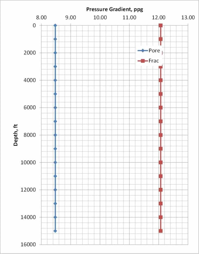
Similarly, the fracture pressure gradient of 0.63 psi/ft corresponds to \(\frac{0.63}{0.433}\times 8.34 \text{ ppg} = 12.13\text{ ppg}\). Figure 2 is a recasting of the data in Figure 1 by plotting the line slope vs depth, or more specifically the pressure gradient in units of ppg vs depth in ft.

Figure 2. This chart shows a constant pore pressure gradient (ppg) and fracture pressure gradient (ppg) increasing as a function of depth (ft).
Using the plot in Figure 2, which of the following mud weights would be safe for the beginning of drilling (at < 2,000 ft)?
8 ppg
Incorrect
9 ppg
Correct
Both 9 and 11 ppg are safe mud weights because they fall within the mud weight window, or they are both > 8.47 ppg and < 12.13 ppg.
11 ppg
Correct
Both 9 and 11 ppg are safe mud weights because they fall within the mud weight window, or they are both > 8.47 ppg and < 12.13 ppg.
13 ppg
Incorrect
Think about whether your answer would change given economic constraints? The higher the mud weight, the more material (clay predominantly) must be added to the mud to get to the desired ppg. This increases the cost of the mud, and an engineer will consequently want to choose the lowest safe mud weight to minimize the cost.
Given economic constraints, then, it makes most sense to start the well drilling at 9 ppg. Look at the chart again and note how the formation pore pressure and formation fracture pressure gradients vary with depth.
Given your choice for initial mud weight, presuming Figure 2 represents your conditions, how would you modify the mud weight as you drill to 15,000 ft?
Increase the mud weight with depth
Incorrect
Decrease the mud weight with depth
Incorrect
Keep the mud weight constant with depth
Correct
Given the pressure gradients are constant with depth, the mud weight that is safe at the surface is safe all the way to the bottom of the hole.
Casing Set Points for the Constant Gradient Case
We have already established that we should use a drilling mud density of 9 ppg to drill our constant gradient case well from surface to Total Depth (TD) of 15,000 ft. As a reminder, the conductor casing is placed to a depth of about 200 ft to establish the foundation for our drilling operation and to prevent interaction between subsequent drilling and shallow groundwater. The surface hole is then drilled, and the required depth for this in Texas is to be no more than 200 ft deeper than the deepest fresh groundwater. We will assume that to be 2,000 ft. Because there are typically no hydrocarbons in the layers to this depth, we might actually drill underbalanced in order to prevent drilling fluid from invading and potentially contaminating groundwater. Once the surface hole drilling is complete, the surface casing is run to the bottom of the hole, and its annulus is cemented from the bottom of the hole to the surface. To verify the entire annulus is truly cemented, the drillers will confirm with visual inspection that they see cement returns at the surface from the annulus.
With both the conductor and surface casing cemented in place, drilling can continue to the target depth of 15,000 ft using 9 ppg mud weight without incident for this mud weight window case. When drilling is complete again, the drill string and bit are removed and the production casing is run in the hole and cemented. Cement generally does not have to be placed all the way back up to the surface for production casing in Texas. The remaining uncemented annulus is left filled with drilling mud above the cement line.
Now with one well successfully drilled and completed, let’s examine a more challenging case. Click on the next page to complete the problem!