


Integrity testing involves several different types of tests done to assess the wellbore prior to production, as well as throughout the life of the project. The amount of testing that needs to take place at the well site is up to the regulatory authority that oversees the project (both state and federal regulatory authorities oversee wellbore sites/projects).
One of the main types of tests that are performed on the wellbore include pressure tests.
Negative Pressure Tests
At the end of the drilling and completion phase, engineers want to make sure that the casing and cement that separate the wellbore from the rock formation can withstand the pressure differential between the borehole (lower) and the hydrocarbon bearing rocks (higher). Engineers purposely lower the pressure inside the wellbore in a controlled manner by replacing the mud within the well by a column of lower density fluid (for example, seawater). This change lowers the hydrostatic pressure pushing against the sides of the wellbore. Prior to perforating the well, there should be no pathway for formation fluids to enter the wellbore, so any measured pressure increase during this test would indicate fluids entering the well, implying a leak.
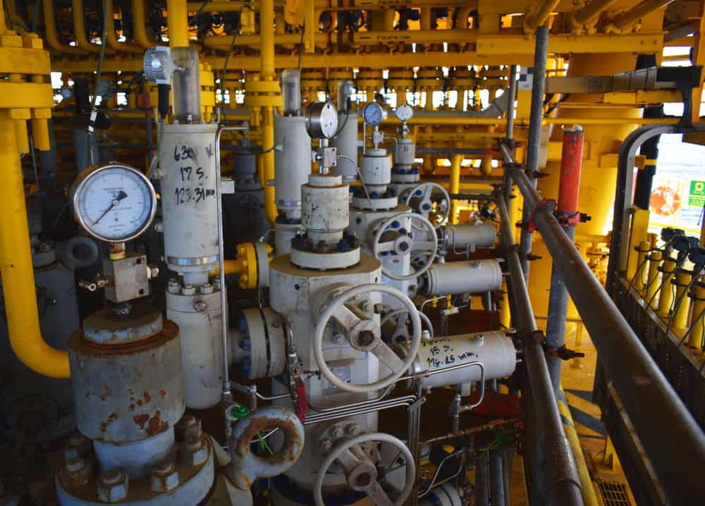
Offshore platforms contain numerous valves and gauges such as on these wellheads.
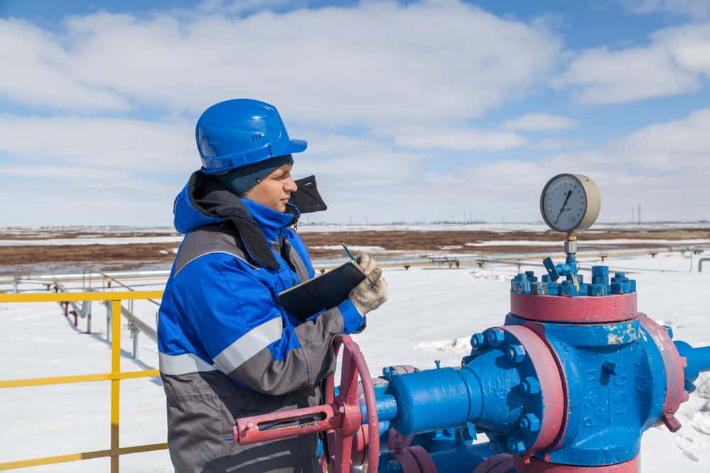
An engineer is reading a wellhead pressure gauge, which enables continuous monitoring of the well throughout its project lifetime.
Once initial integrity testing is successfully completed, production can begin. Throughout the life of the project, engineers often use fiber optics to continually evaluate the well. Fiber optics are used to measure not only the pressure, but also the temperature and acoustic conditions within the wellbore. Routine pressure testing is also conducted throughout the duration of the production lifecycle.
Mechanical Integrity Tests for Injection Wells
Class II injection wells used to inject fluids associated with the oil and gas industry fall into one of three categories: disposal wells (for example to dispose of water produced during oil production), enhanced recovery wells (for example, wells to inject steam for enhancing production), and hydrocarbon storage wells (for example, gas storage wells such as described in the case study at the end of this lesson). A mechanical integrity test (MIT) is a test consisting of two parts which is conducted on injection wells to insure there is no significant leak in the well and that the mechanical components of the well function in a manner protective of the environment and human health.1Graves, B. (2018, June). Mechanical Integrity Testing (MIT). U.S. Environmental Protection Agency. https://www.epa.gov/sites/production/files/2018-06/documents/mechanical_integrity_2018_-_brian_graves.pdf
Pascal’s Law and pressure tests
The most common internal MIT is the standard annular pressure test. This test relies on the concept that pressure applied to a closed system with a fixed volume like an injection well annulus (sealed at the bottom with a packer and at the top with a wellhead) will be maintained even once the pressure source is removed, if there are no leaks in the system. Pascal’s law is a principle in fluid mechanics given by Blaise Pascal in 1653 that states that a pressure change at any point in a confined incompressible fluid is transmitted throughout the fluid such that the same change occurs everywhere. Pressure applied to a container, such as a sealed injection well annulus, is transmitted with equal force throughout the fluid filled container.
Graph Analysis
Below, you can see the results of an internal mechanical integrity standard annulus pressure test. The goal is to test the tubing, casing, and packer for leaks. Testing requirements may vary but typically the casing/tubing annulus is pressurized to the maximum allowable injection pressure to ensure the casing can withstand this pressure should the tubing or packer fail. If the pressure can be maintained for a specified period of time within a specified percentage of loss or gain, the well is deemed to have passed.2Graves, B. (2018, June). Mechanical Integrity Testing (MIT). U.S. Environmental Protection Agency. https://www.epa.gov/sites/production/files/2018-06/documents/mechanical_integrity_2018_-_brian_graves.pdf
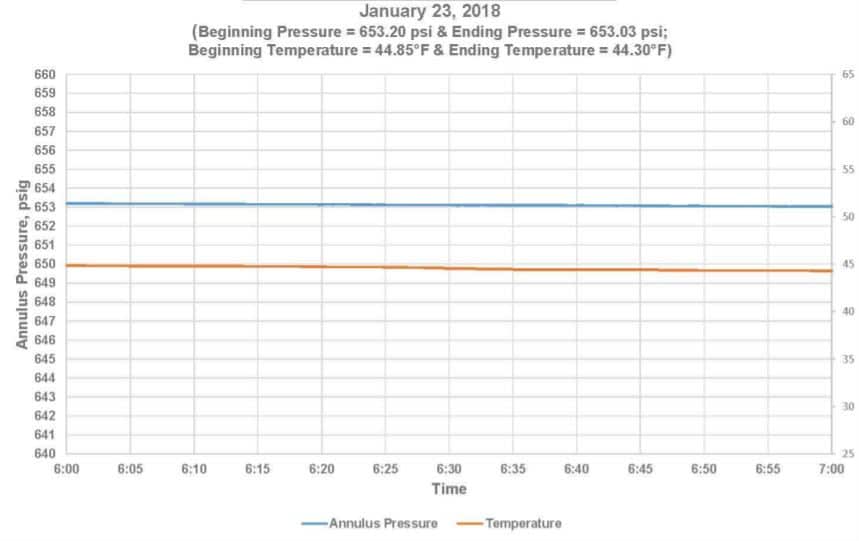
Annulus pressure and temperature graph
The test length is typically 30 minutes to an hour. In this example,3Graves, B. (2018, June). Mechanical Integrity Testing (MIT). U.S. Environmental Protection Agency. https://www.epa.gov/sites/production/files/2018-06/documents/mechanical_integrity_2018_-_brian_graves.pdf the test was run for an hour as noted on the x axis. A pressure loss of > 5-10% is typically considered failure.
Examine the graph and answer the following questions about the pressure test.
Image Credits
- Construction,On,Offshore,Wellhead,Platform,,Energy,And,Petroleum,Industry,,Oil: Mr.PK/Shuttershock.com
- Oil,,Gas,Industry.,The,Mechanic,-,The,Repairman,,Gas,Production: Evgenii Mitroshin/Shuttershock.com